Lab Experiments with AoE
(Art of Electronics)
DL1GO
German Amateur Radio Station, DOK C12, Loc JN58AT, CQ 14, ITU 28
www.gollreiter.eu
| Contact | Impressum
Filter Application I: Garbage
Detector
Problem Statement:
A standard power line transformer produces a lot of noise. In this experiment
the noise should be made visible by the use of a simple passive RC-high-pass
filter.
The Circuit:
An excellent introduction to the subject, and a lab setup is described on page
83 in the reference book:
Thomas
C. Hayes, Learning the Art of Electronics, Cambridge University Press, 2016
The print transformer
„SPITZNAGEL Part Number 02206“ has a primary 220V voltage at 50 Hz (Europe) and
a secondary 9.8V voltage. The datasheet is here:
https://www.buerklin.com/datenblaetter/C090525_TD_de_eng(1).pdf?ch=18598
A simulation of the
transformer with noise figure and an appropriate simulation can be found in EveryCircuit with user “rigo59”:
Lab Setup:
The print transformer is shown in Fig. 1. The secondary pins of the
transformer are directly connected to the RC-high-pass filter, shown in Fig. 2 and simulated in EveryCircuit.
Experiment 1:
When the transformer is connected to the power line a short-term back-EMV pulse
with a peak of 25V is measured with the digital volt meter. The non-load
voltage is 9.8V. Unfortunately I’m not able to capture the pulse with the
oscilloscope.
Experiment 2:
Now I measure the output
signal of the transformer with the oscilloscope in both time (T) and frequency
(F) domain.
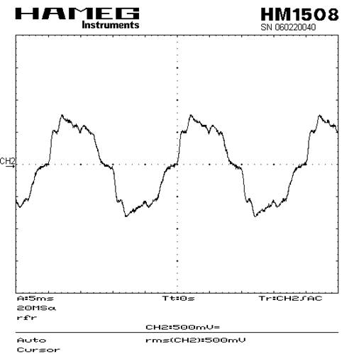
T: The shape of the transient
signal is close to what the AoE reference book describes as „ (it) look(s) …
more or less like a classical sinewave“. Obviously there are 3-rd, 5-th, 7-th, 2k-1… harmonics in the signal, which gives the signal a kind
of rectangular shape. See Fig. 130 for
details.
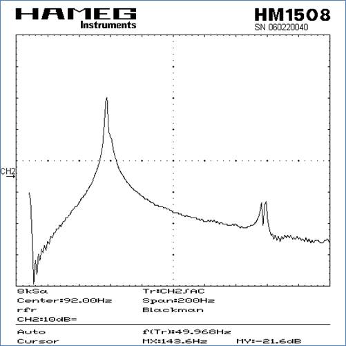
F: The measured impulse
response in the frequency domain is shown in Fig. 131. The scaling is dB(V) above
frequency. At 50 Hz the voltage is 18dBV (7.9V).
Experiment 3:
Now the passive RC high-pass
is connected at the output pins of the transformer. I use a 3dB-frequency of f3dB
= 1000 Hz, with R = 16.5k and C = 10nF. The damping of the filter is 26dB
at 50 Hz. The impulse response in the time domain shows Fig. 132. The remaining signal has 500 mV (RMS). In the
frequency domain the noise is clearly visible by comparison of Fig. 133.
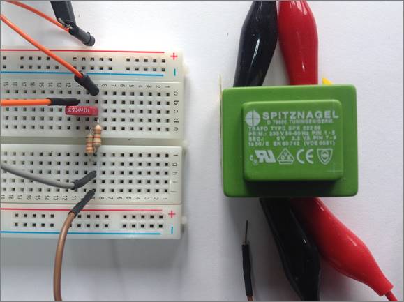
Figure
1:
Transformer with passive RC high-pass on breadboard
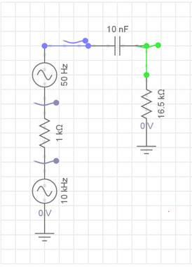
Figure
2:
Passive RC high-pass connected to an emulation of a transformer, a 50 Hz
generator signal superimposed with a 10 kHz noise signal
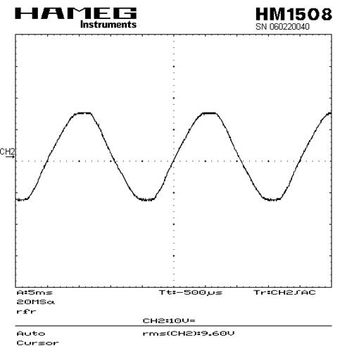
Figure
130:
Output signal of the transformer looks more or less like a classical sinewave
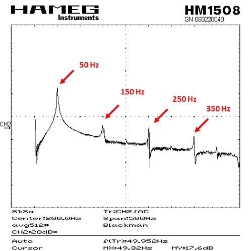
Figure
131:
Output signal of the transformer in the frequency domain
Figure
132:
Output signal of the transformer behind the high pass in the time domain
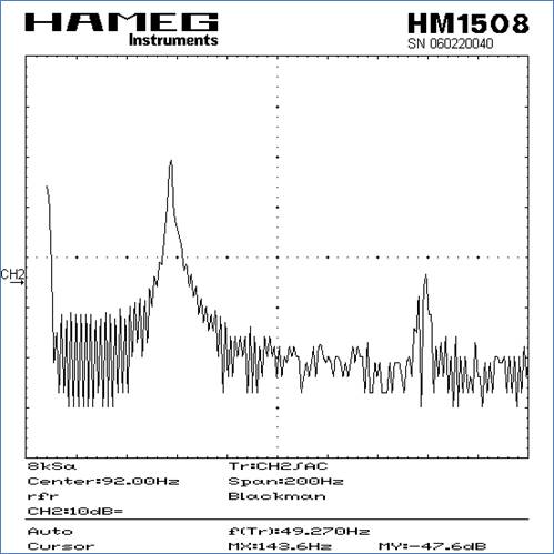
Figures
133:
Output signals of the transformer at the input (left) and output (right) of the
high pass in the frequency domain
Created by dl1go on March 24, 2016 - 14:00 | Lab Experiments with AoE