Lab Experiments with AoE
(Art of Electronics)
DL1GO
German Amateur Radio Station, DOK C12, Loc JN58AT, CQ 14, ITU 28
www.gollreiter.eu
| Contact |
Impressum
Audio Bandpass
Problem Statement:
Design a passive audio RC bandpass for the frequency range between 1500 – 8000
Hz. The external load to the bandpass is greater or equal to Rext_load
= 1M.
The Circuit:
An excellent introduction to the subject, and a lab setup is described on page
103 in the reference book:
Thomas
C. Hayes, Learning the Art of Electronics, Cambridge University Press, 2016
A simulation of the passive
RC bandpass can be found in EveryCircuit with user “rigo59”:
The bandpass is designed as
a cascade of a RC high-pass and a RC low-pass filter. The circuit plan of the
bandpass is shown in Fig. 1.
Lab Setup:
The lab setup with a breadboard is shown in Figure 2 and the impulse
response of the bandpass filter on a digital scope in Fig. 3. The generator is set to sinewave with amplitude of 4V, (Vss = 8V).
Experiment 1:
The design of the second stage of the bandpass consists of a low-pass with the
3dB frequency f3dB = 16.000Hz = ( 2 x 8000Hz). The value of the
resistor is set to RLP = 100k, because it is a factor 10 lower than
the 1M external load (see reference book for the details of a “factor 10
rule”). The value of the capacitor is calculated with the formula f3dB =
1 / ( 2 * pi * R * C). For the practical use an appropriate value is 100pF.
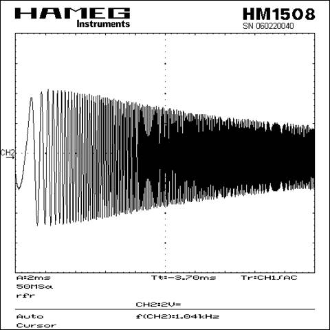
The response of the low-pass
filter in the frequency domain in the range of 490Hz to 30.000Hz is shown in Fig. 143.
Experiment 2:
The design of the first
stage of the bandpass consists of a high-pass filter with the 3dB frequency f3dB
= 750Hz = ( 1/2 x 1500Hz). The value of the resistor is set to RHP
= 10k, again because of the “factor 10 rule”. The value of the capacitor is
calculated with the formula f3dB = 1 / ( 2 * pi * R * C). For the
practical use an appropriate value is 20nF.
The response of the
high-pass filter in the frequency domain in the range of 490Hz to 16.000Hz is
shown in Fig. 142.
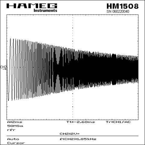
Experiment 3:
The bandpass is realized as
a cascade of a high-pass filter (1st stage) and a low-pass filter (2nd
stage). The impulse response in the frequency domain in the range 490Hz –
30.000 Hz in presented in Fig. 144.
Figure
1:
Passive RC bandpass designed for a frequency range between 1.5kHz and 8kHz
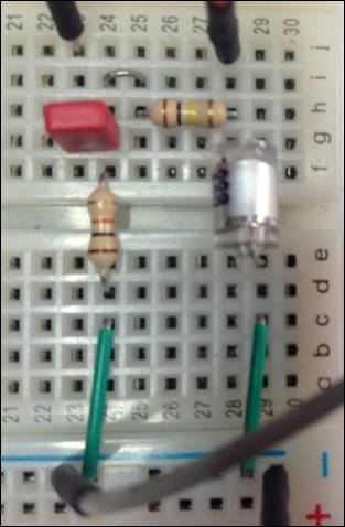
Figure
2:
Lab setup of the bandpass filter on a breadboard
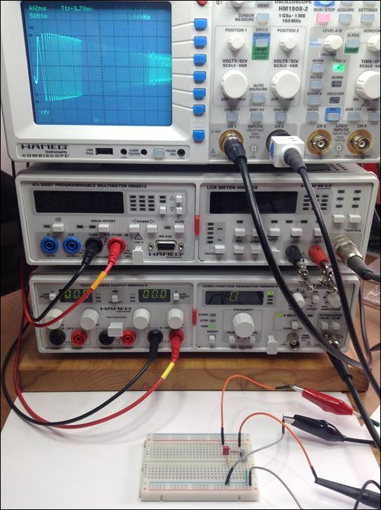
Figure
3:
Lab setup with digital scope showing the frequency domain of the bandpass
filter
Figure
143:
Low-pass filter in the frequency domain range 490Hz - 30.000Hz (Experiment 1)
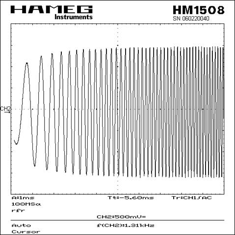
Figure
142:
High-pass filter in the frequency domain range 490Hz - 16.000Hz (Experiment 2)
Figure
144:
Bandpass filter in the frequency domain range 490Hz - 30.000Hz (Experiment 3)
Created by dl1go on March 28, 2016 - 22:00
| Lab Experiments with AoE